YAMAHA MEASURE REPORT

Note: The information is only for YAMAHA ________________ ______.

REF. No. 84055 ½

MODEL RD500 (1984 model) FILE

SUBJECT Abnormal Vibration/Engine Noise

  1. Symptom

When throttle is closed in a cruising ride (5,500 - 7,000rpm) ________ is _____

notice an engine noise and feel vibrations on the footrests.

(As explained in our TSI No. NC-84005, this was referred to as being "IRREGULAR

COMBUSTION", which is in itself not a problem.)

  1. Factory Measure

In the 1984 RD500and RZ500, the balancer is driven by the lower crank, whereas

in the 1985 models this will be driven by the upper crank. This should reduce

to a significant degree the engine noise and the footrest vibrations.

  1. Field Measure

If there are customers who will not be satisfied with the explanation given in our TSI No. NC-84005, replace the balancer with that of the 1985 spec. (Balancer driven by the upper crank) is per the following procedures.

  1. Remove the under-cowl and right side panel. Then drain the transmission oil and coolant.
  1. Remove the kick crank, water pump assembly, and crankcase cover.
  1. Remove the clutch nuts and then the clutch assembly.
  1. a) Remove both upper and lower primary drive gear nuts.
    1. Remove both upper and lower primary drive gears.
    2. Remove both upper flywheel and lower balancer drive gear.
    3. Mark the flywheel at A using a felt tip marker or the like as shown.
    4. Mark the balancer drive gear at B (13th tooth from the alignment mark) and at C (18th tooth from the alignment mark) using a felt-tipped marker or as like shown.

img00001.gif (6438 bytes)

MODEL RD500 (1984 model)

SUBJECT Abnormal Vibration/Engine Noise

5) a) Replace the flywheel and balancer gear.

  1. Align mark B on the balancer drive gear (13th tooth) and the alignment mark on the balancer gear.
  2. Install both upper and lower primary drive gears same as before. (* Mack coated primary drive gear is installed on the lower.)

d) Tighten upper and lower dive nuts (torque: ____ kg-_).

img00002.gif (5996 bytes)

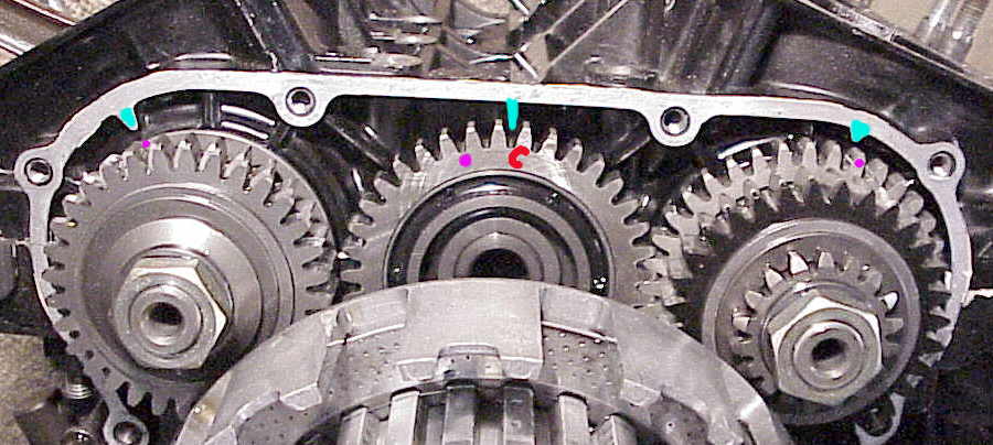
6) a) Align markC on the balancer drive gear (18th tooth) and the alignment mark on the case.

  1. Align mark A with the case alignment mark.
  2. Install the clutch assembly and tighten the clutch nuts and bend the lockwasher tab.

img00003.gif (6697 bytes)

  1. Reinstall the crankcase cover, water pump assembly and kick crank case.
  1. Fill in coolant and transmission oil.
  1. Warranty

Labor - 0